The BGL is used to trace and locate ground faults on a live DC system, without sectionalizing any circuit.
STEP 1 Turn on the BGL. This instrument is battery operated or can be used also connected to the power supply. After turning on the unit the LED “In Progress” will illuminate for a while. If it is being operated from the internal battery the LED “Overrange” will illuminate as well when the charge is over 90%.
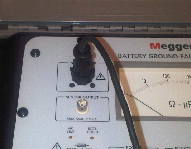
STEP 2 Test Lead Connection. Connect the current sensor and output lead set to the instrument.

STEP 3 Test Leads Connection to Battery System. The output test lead set should be connected to the battery system in the following order:
- Connect the black and green ground wires to earth ground for both a ground and safety.
- Red clip to positive or negative battery bus bar. A small spark may occur when connecting to battery terminals and the LED “Warning > 30VDC” may turn on.
- Clamp the current sensor around the red cable from the output lead set.

STEP 4 Measure total resistance to ground. After connecting the clamp, set the “Function” switch to resistance position, then wait for VALID LED to illuminate.
Verify you can measure the ground fault and note the value.
With the current sensor around the red cable of the lead set, the instrument will measure the total parallel resistance to ground of the battery system. This includes all leakage paths from positive and negative side. If this resistance is in excess of 10 Kohms, the chances of finding any problem is limited.
STEP 5 Measure resistance of each branch. If the total resistance measured in step 4 is below 10 Kohms the next step is to measure the resistance of each branch of the system to trace down on which is the fault or faults. Troubleshoot the lowest resistance branch first.
To measure the resistance of each branch disconnect the clamp from the red cable of the output lead set and clamp it to the first branch to be measured, wait for “Valid” LED to illuminate and take note of the resistance to ground of this branch. Repeat this for all branches and compare them to determine which branch has the lowest resistance.
Once a branch has been identified further measurements should be done downstream of it to locate the specific point of fault in the branch.
STEP 6 Terminating measurements. Once a particular panel has been measured and you need to move to another panel or you have completed the test, the instrument needs to be disconnected. To remove the test leads follow the sequence below:
- Remove the clamp from the branch
- Disconnect the red clip from battery bus bar. If the “Warning > 30VDC”LED illuminates, connect the red clip to ground until the led turns off.
- Disconnect the black clip from ground.
- Disconnect the green clip from ground.
- Turn off the unit and disconnect it from the power supply if it is being used.
THE BGL
Simplify fault location. This instrument was developed to detect, track and locate ground faults on battery systems – without resorting to sectionalizing! Model BGL tracks and locates ground faults on live or dead battery systems. To save hours of unnecessary troubleshooting, the BGL readily differentiates between the resistive fault currents and capacitive charging currents. This feature allows the instrument to detect and track leakage paths, even in the presence of surge-suppression capacitors.
